Plastic Lid Option
1 - Mechanical Installation
General Idea
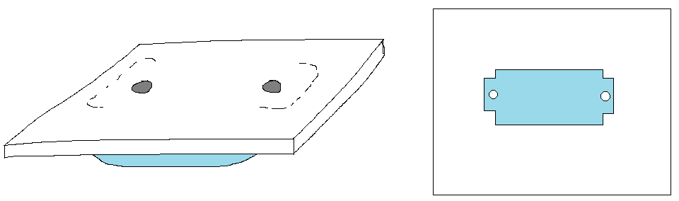
Placement
When installing the Radar & Tilt Module underneath a plastic lid, consider the following:
Identify a flat mounting area on the underside of the cover where the back of the device can be fully supported and positioned level. A ribbed surface is acceptable, provided the ribs offer sufficient and even support.
Ensure there is sufficient space to accommodate two M6 mounting bolts, one on either side of the device. For ribbed covers, the bolts may pass through the ribs, provided they offer adequate structural support.
Mount the device as close to the centre of the cover as possible, ensuring the radar sensor has an unobstructed view of the liquid surface. Off-centre mounting is acceptable where obstacles prevent central placement.
If the device is mounted off-centre, make sure the manhole cover has a keying insert so it can only be installed in one orientation. If there is no keying insert, add a clear alignment mark to ensure the cover is always returned to the same position
Mounting Procedure
Hold the device against the underside of the manhole cover and mark the mounting hole positions using one of the following methods:
Direct marking: Use a paint marker to mark the two mounting holes from underneath the cover
Measurement: Identify the ribs or mounting points where the M6 bolts will pass through, then measure and transfer their positions to the top of the cover
Drill two 7mm holes through the cover at the marked positions
Secure the device using the following stainless steel A2 components, assembled in order:
Insert two M6 bolts (e.g. Würth Art. No. 0096665), each with an M6 washer (e.g. Würth Art. No. 04096), through the cover from above. Select the appropriate bolt length based on the cover thickness.
Position the device onto the protruding bolts underneath the cover
Fit an M6 washer and M6 nut (e.g. Würth Art. No. 03226) onto each bolt, then tighten to secure the device in place
Ensure the device is securely mounted and level when the cover is in its closed position
Required Measurements
Take the following measurements based on whether the manhole or reservoir is cuboid or vertically cylindrical. Also note whether it includes a chimney (narrow access opening) and, if so, whether the device is installed within the chimney, as this affects the required measurements.
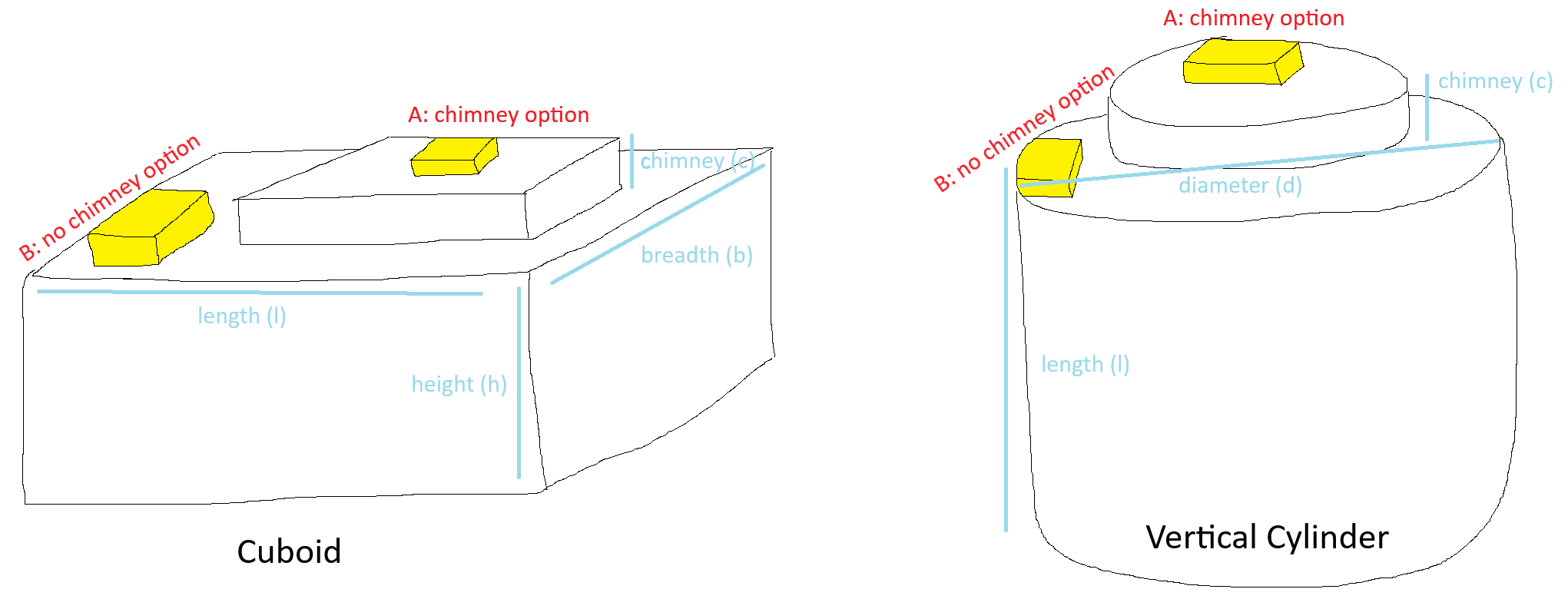
A minimum chimney height of 5cm is generally configured, even where no physical chimney is present. This provides earlier indication of 100% level and helps prevent the device from becoming submerged when the reservoir or manhole reaches full level.
2 - System Commissioning
Device Setup
Activate the IoT Pro device according to the communication network being used:
Platform Setup
Make sure that you have access to the IoT Pro Cloud Platform. Follow the Getting Started guide to familiarize yourself first.
Open the IoT Pro Dashboard Mobile Application and log in
Navigate to Assets and select Create Asset
Under Asset Name & Device:
Enter an Asset Name
Select Application:
20_IOTPRO-RadarDistanceAirTiltSelect Device: choose the device installed in the previous section
Assign the asset to a group, if required
Complete the Asset Information fields as required
Under Asset Images, use Take Photo to capture the required photos of the completed installation
Under Advanced Fields, configure the following:
Bottom Offset (cm): 0
Chimney Height (cm): enter the chimney height measured during installation
Asset Shape: Vertical Cylinder or Cuboid and enter the measurements taken during installation
Supply/Discharge
Discharge for sewage, wastewater, or similar applications
Supply for water, diesel, fuel, or similar applications
Click Create Asset
Open the IoT Pro Device Setup Mobile Application, reconnect to the installed device, and select Send Message to transmit a new reading
Return to the IoT Pro Dashboard Mobile Application and navigate to Live Map to view your Asset
Use the Level Supply or Level Discharge Dashboard to view the manhole or reservoir's level readings and trends