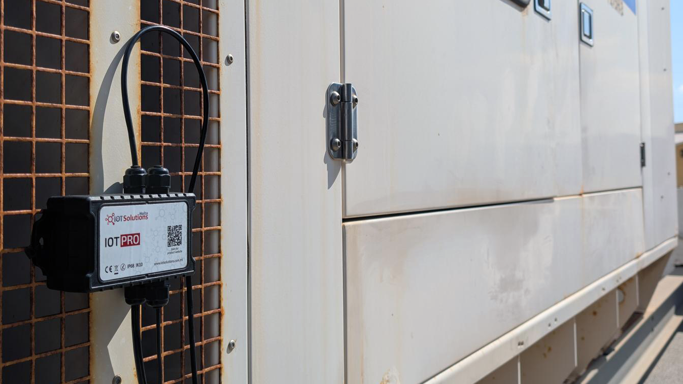
IoT Pro Generator Module
Monitor fuel levels, receive power loss and recovery alerts, and automate test runs to ensure your generator is always ready when needed.
Installation Guide
This guide will walk you through installing the IoT Pro Generator module in a standard generator. The process typically takes 1-2 hours for a standard installation.
This installation must be performed by a qualified electrician or authorized technician only due to high voltage hazards
Before you begin
Before your first installation, complete the IoT Pro Quick Start in the office to familiarize yourself with the process
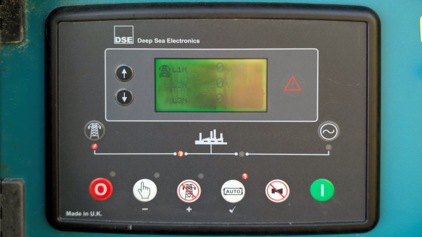
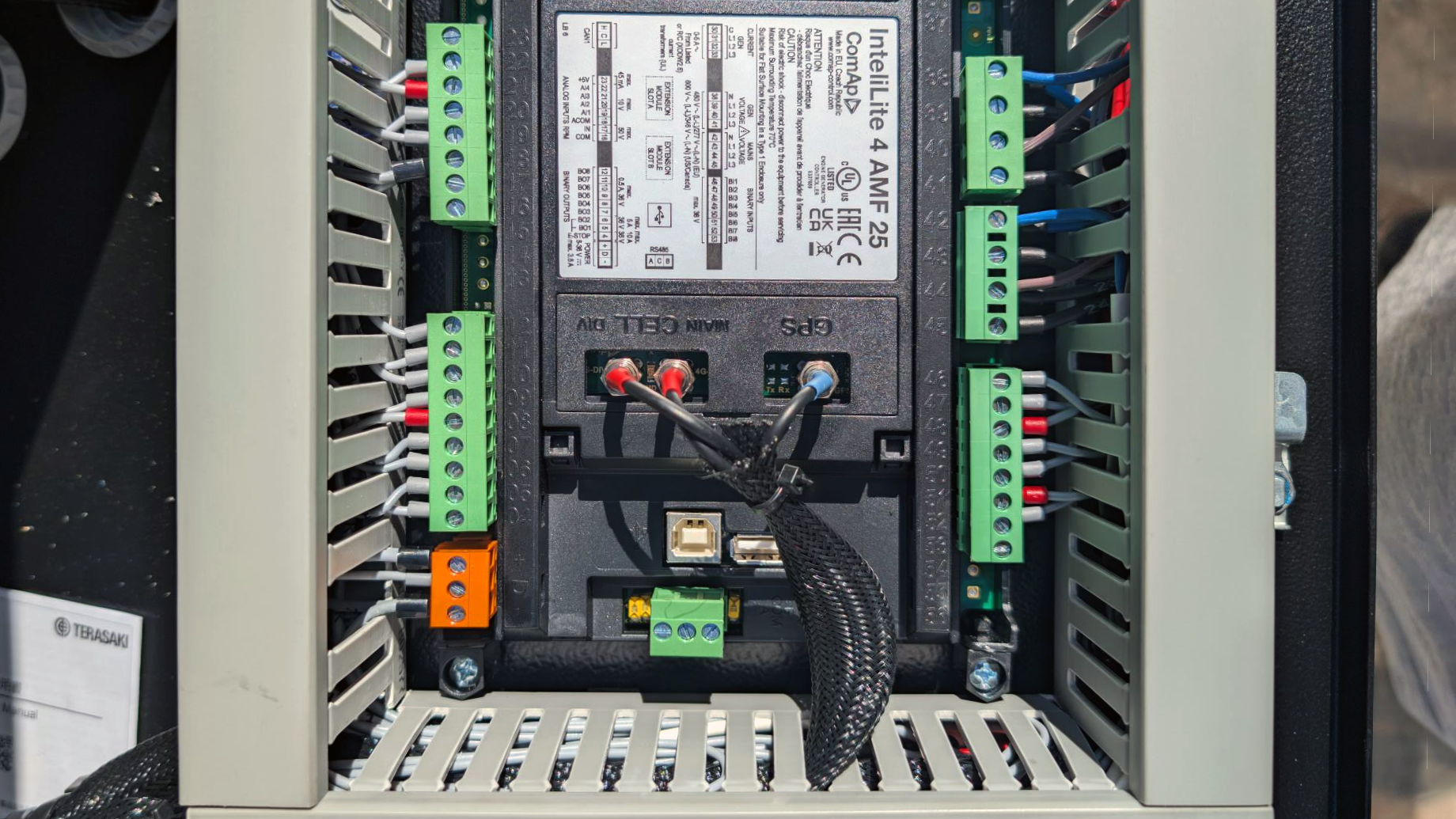
Safety First: Locate the generator control panel and set the mode to STOP (instead of AUTO). This prevents the generator from starting automatically during the installation.
Installation Tips: Throughout this installation, refer to:
Cable Management - for proper cable routing techniques
Wire Extensions - if you need to extend any sensor cables

Installing Sensors
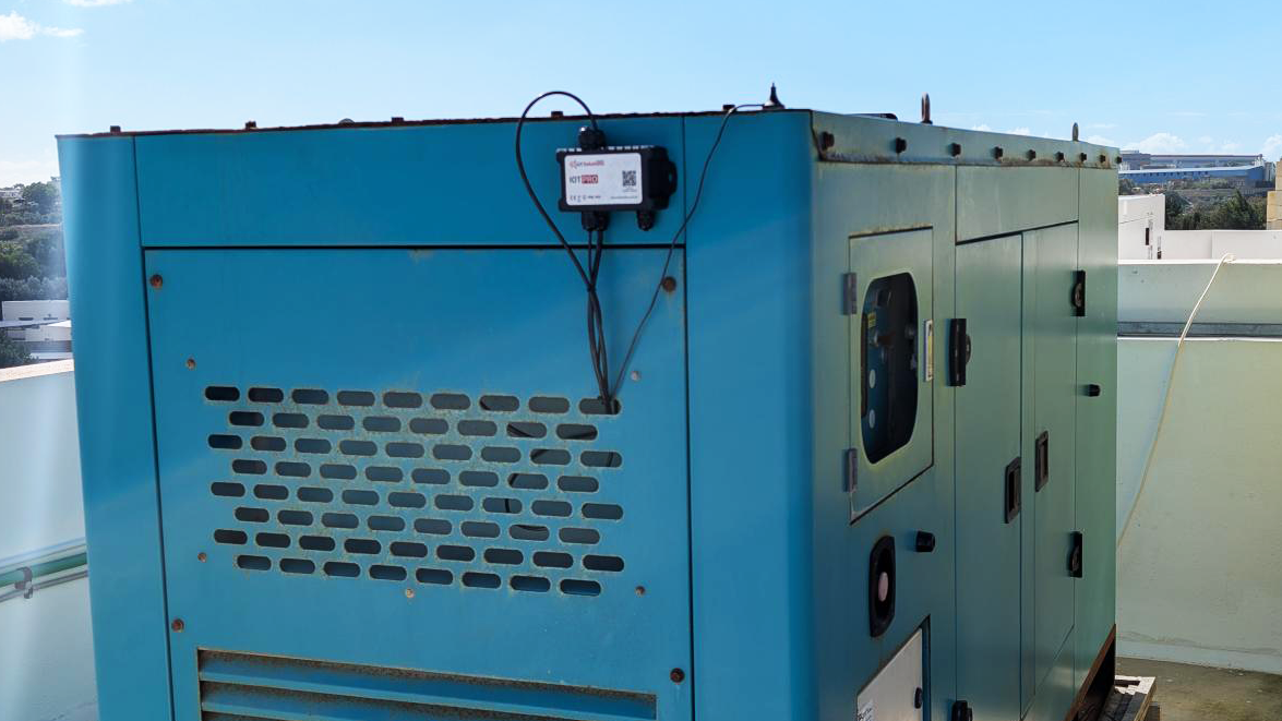
Start with installing the sensors first, before installing IoT Pro. We'll begin with the fuel tank capacitive level sensor and engine temperature sensor. This allows you to position the IoT Pro device optimally for both sensor cable runs, avoiding the need for junction boxes or cable extensions. Refer to Reference Images for guidance.
Fuel Tank Capacitive Level Sensor
Preparation
The capacitive level sensor probe length can be adjusted according to the fuel tank depth. Up to 2/3 of the sensor can be cut (for example, if the probe is 300mm long, it can be shortened to 100mm).
Make sure to account for the length of the adapter depending on the installation method.
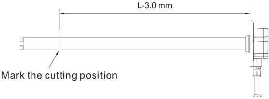
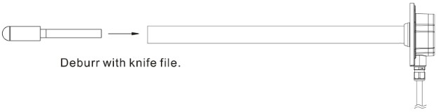
Instructions for cutting the probe:
Mark the cutting position 3mm shorter than the tank depth (L)
Cut the probe at the marked position with a saw blade - do not remove the bottom plug before cutting.
To cut the probe, put the probe in a vice and make sure to hold it with a thick cloth or cardboard to not damage the paint on the probe, or the probe itself
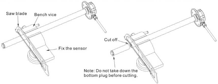
Debur with knife file the cut probe - inside of the tube should be kept clean, burrs dropped into the tube must be cleaned to remove risk of blockage.
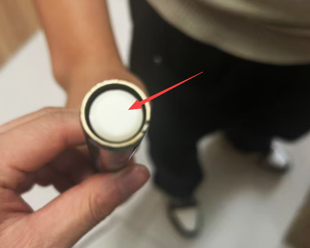
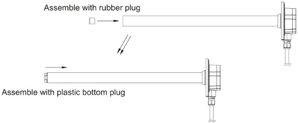
Remove the beige rubber plug from the cut-off section of the original probe and transfer it to the new probe. Ensure that the beige plug is firmly secured to the internal electrode. This maintains the proper gap between the inner and outer electrodes and allows fuel to smoothly enter the sensor probe. Finally, re-assemble the black bottom plug.
Calibration
Prepare a plastic bottle (a regular 2L soft drink bottle with a wide cap works well) or diesel container which is deeper than the maximum calibration length.
Instructions for calibrating the probe with the provided calibrating tool:
Do not power on the probe
Remove the top Phillips head screws at the top of the sensor and connect the calibrator to the probe
Turn on the calibrator (ensure that this has a 12V A23 battery) and that the LED on the calibrator turns on
Insert the probe into the bottle so it is submerged to the same depth the probe will be submerged at when the fuel tank is full, taking into account the adapter height offset depending on the installation option, and wait for 30s
Press 'F' on the calibrator and release when the calibrator LED starts blinking
Wait for the blinking led to stop
Remove the probe and drain in free air for 30s in a well-ventilated area away from ignition sources. Clean off any excess fuel.
Leave your probe in free air for 30s (This way the empty position 0% level will be when no Diesel is touching the capacitive sensor)
Press 'E' on the calibrator and release when the calibrator LED starts blinking
Wait for the blinking led to stop
Turn off and remove calibrator
Close the top cover with screws again
The sensor may now be installed and wired to IoT Pro.
Installation Methods
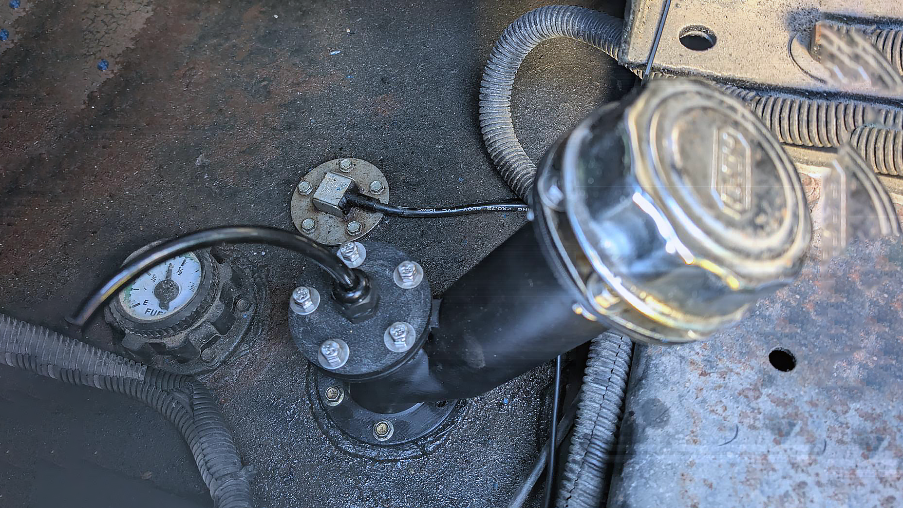
Locate the fuel tank inside the generator and choose one of the following installation methods (listed in order of preference):
Option A: Use an existing free inlet or replace the existing mechanical gauge sensor
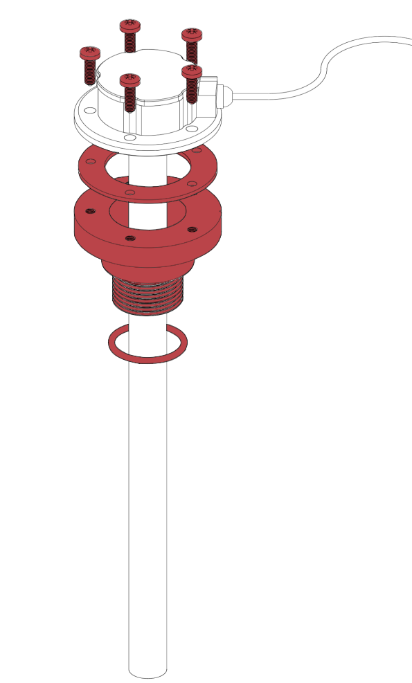
Use the provided adapter with provided gasket and O-ring to ensure a proper seal
1 inch to 3 inch BSP adaptors can be provided, get in touch with our team members from IoT Solutions Website - Contact Us for custom adaptors
Use the provided M5 stainless steel A4 self-drilling screws to attach the capacitive sensor to the provided adaptor
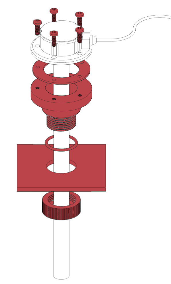
Option B: Drill a hole into the lid of the tank or into a flat removable piece of the tank
First remove the lid or the removable piece
Identify the best hole location for the sensor - there should be no obstructions to the sensor once installed into the tank
Drill a pilot hole - use the appropriate drill bit material according to the lid or piece material
Enlarge the hole with a cone drill or hole drill depending on the material thickness to 34 mm diameter
Install the capacitive sensor as shown with the provided adaptor, nut, gasket and O-ring
Option C: Install a 3D printed custom adapter fuel inlet (Get in touch with our team members from IoT Solutions Website - Contact Us)
The 3D print can be customized to your tank specifications
Option D: Drill an additional hole directly into the tank (least preferred - tank must be emptied and fully ventilated before drilling to prevent fire hazard)
Identify the best hole location for the sensor - there should be no obstructions to the sensor once installed into the tank
Drill a pilot hole - use the appropriate drill bit material according to the tank material
Enlarge the hole with a cone drill or hole drill depending on the material thickness to 31 mm diameter
Use a 1 inch BSP tap to thread the drilled hole
Install the capacitive sensor as shown in Option A with the provided 1 inch adaptor, gasket and O-ring
Important: Bleed all air from fuel lines before closing the system
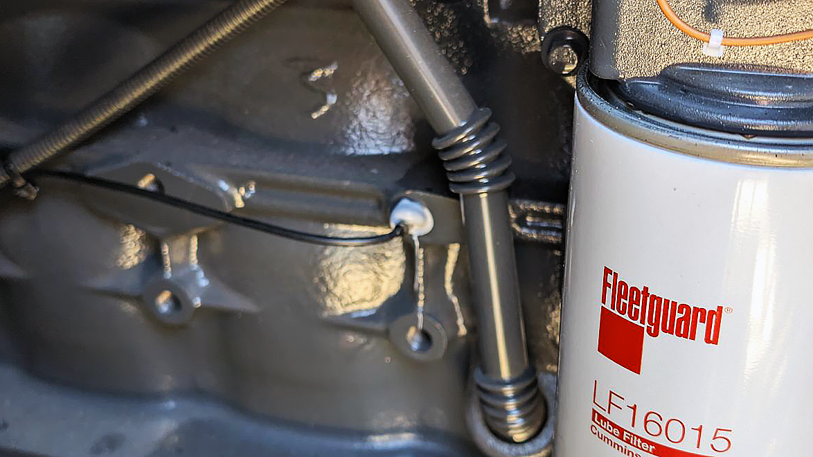
Engine Block Temperature Sensor
Locate a suitable hole in the engine block near the cooling channels
Apply Bond and Seal adhesive (Wurth Article No. 089010011 or Article No. 0893236110)
Insert the temperature probe firmly into the hole
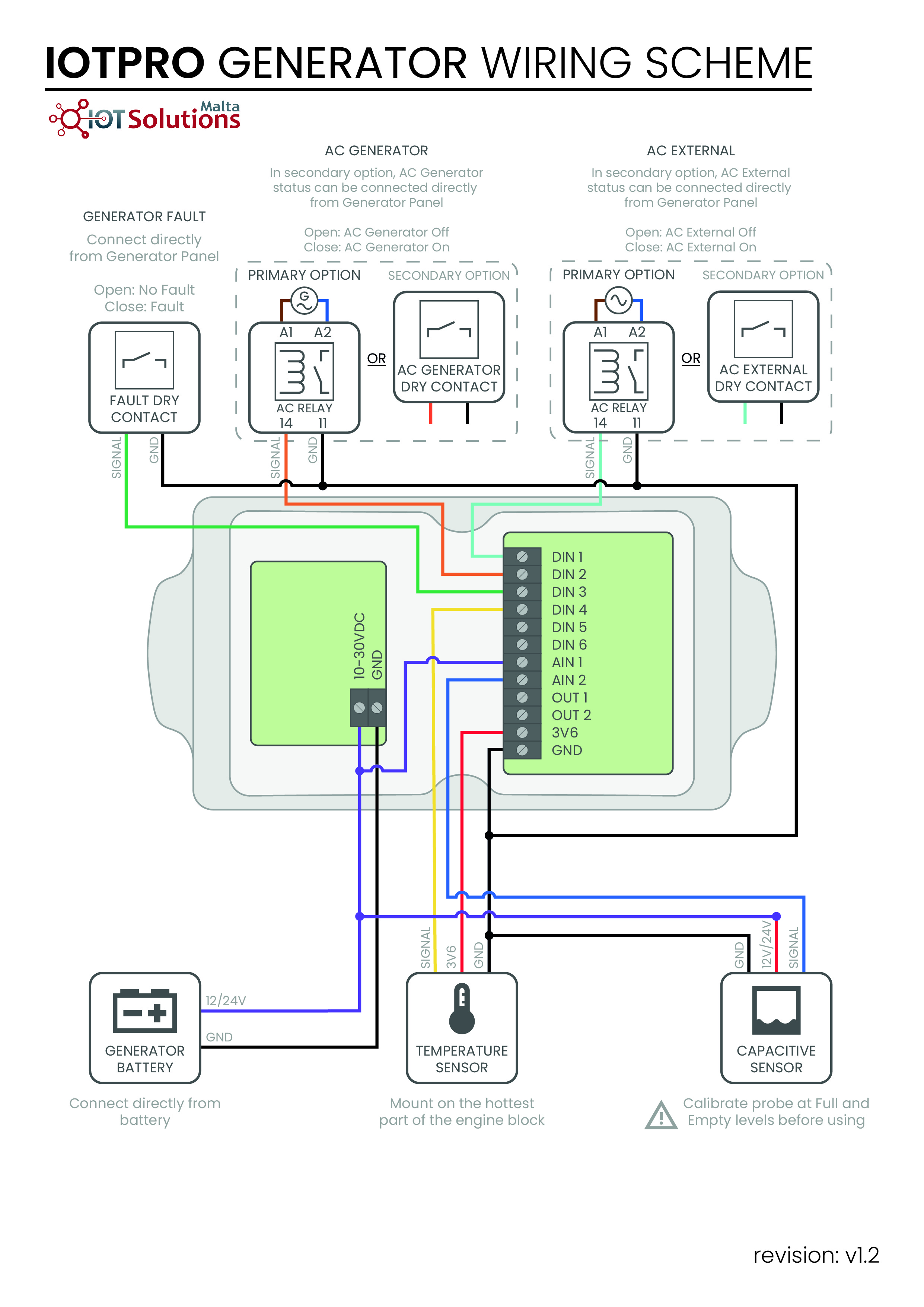
Electrical Connections
Turn off the main supply to generator before proceeding
Note: A complete wiring diagram is available at the end of this guide for reference
Use a separate multi-core cable for each connections. Mount the DIN relays securely inside the control panel.

AC External Input (DIN1)
Connect to the AC feed entering the generator, ideally before any protection devices:
Preferred: Connect directly to the battery charger input
Alternative: Wire from the control board where the generator receives its AC mains feed
Generator AC Output (DIN2)
Tap into a single phase of the generator output:
Preferred: Connect directly after the MCBs (main circuit breakers) at the generator output
Alternative: Tap from the control board if direct access is not possible
Fault Detection Input (DIN3)
Locate the dry contact relay on the generator control board that activates during fault conditions
Wire this contact to DIN3 and Ground
Fuel Tank Capacitive Sensor
Route the sensor cable to the IoT Pro device and connect as follows:
AIN2: Blue wire
12V/24V: Red wire
GND: Black wire
Engine Temperature
Route the sensor cable to the IoT Pro device and connect as follows:
DIN4: Yellow wire
3V6: Red wire
GND: Black wire
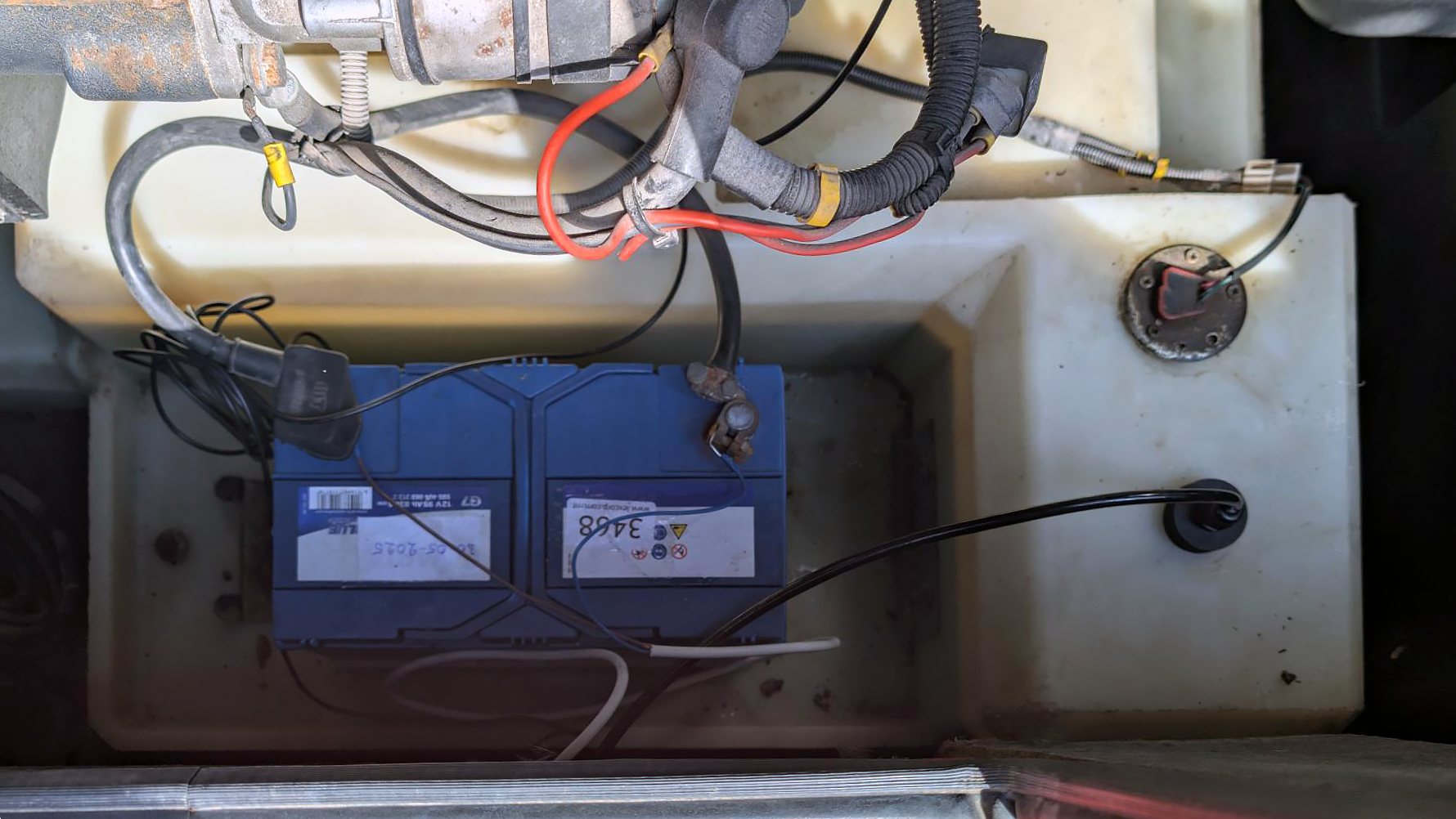
Power Supply
Use a 2-core 0.5mm² cable
Connect one end of the cable to the power board’s 2-pole terminal block (red = +V, black = GND)
Connect the other end directly to the generator's 12V/24V battery before any main switch
Terminate the cable using 6mm ring crimp connectors
Secure to the battery terminal lug nut
Inside the IoT Pro device, bridge the positive supply (+V) to AIN1 as required for battery voltage sensing
Cable Management
Internal/External Routing
Route cables through the generator's soundproof insulation wherever possible
This provides neater installation and protects cables from chafing
Cable Securing
Apply fiber/duct tape to any cables on the generator exterior for additional security and safety
Wire Extensions
If you need to extend the pressure or temperature sensor cables:
Use heated solder joints
Wire extensions should be done inside the generator for added environmental protection
Reference Images
Testing and Commissioning
Initial Verification
Connect to the IoT Pro device using the mobile application
Confirm that Peripherals is OK
Verify the Application Data
Software Platform Configuration
Log In to your IoT Pro Software Platform
Navigate to Assets
Create a new asset whilst taking particular note of the following settings:
Choose the Device ID based on the label on the device
Asset Shape: Cuboid
Enter tank dimensions (measure from inside the tank)
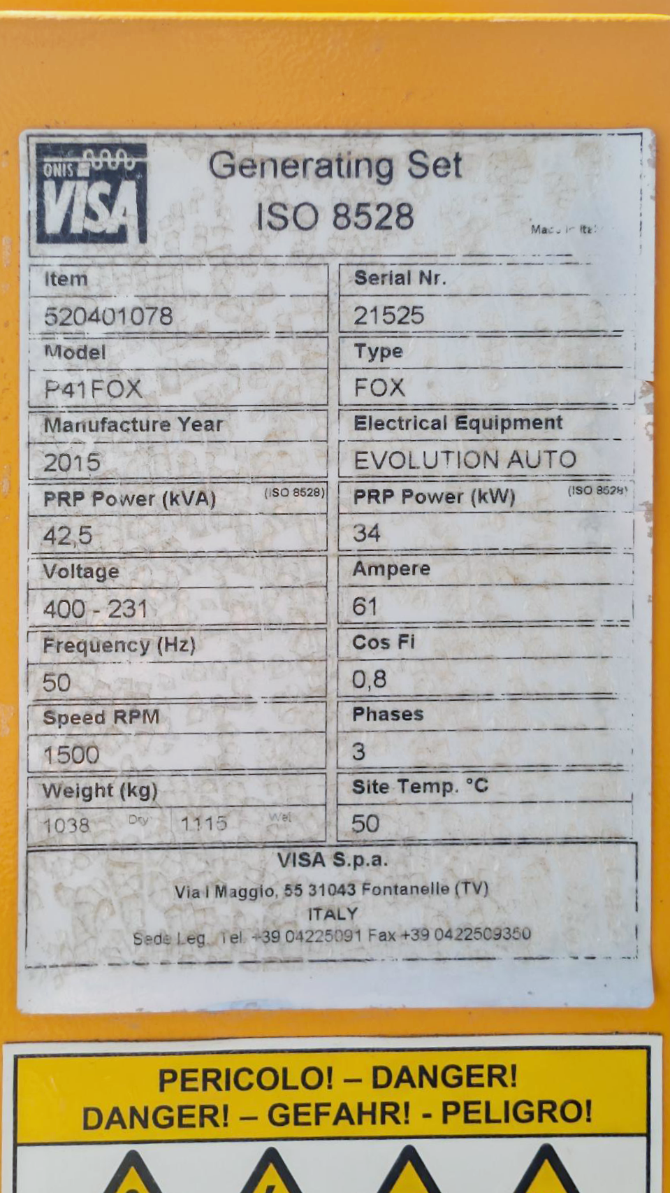
Tip: To find the fuel tank capacity (litres) and full-load fuel consumption (litres/hour), first locate the generator’s model number on its identification plate (similar to the example below). You can then use an AI tool to retrieve this information and confirm that it makes sense.
Conclusion
Double-check all connections
Switch the generator mode from STOP back to AUTO
Activate the IoT Pro Device and Send a Message as explained in IoT Pro Quick Start
Test the generator operation
Verify that all sensor readings appear correctly on the dashboard
Resume normal operation
Installation Complete!
Your generator monitoring system is now active. Monitor your asset through the IoT Pro Software Platform.
Appendix
Wiring Diagram