IoT Pro External Antenna
What you’ll need
1 mm drill bit (if an additional hole for an antenna needs to be made)
7 mm drill bit (if an additional hole for an antenna needs to be made)
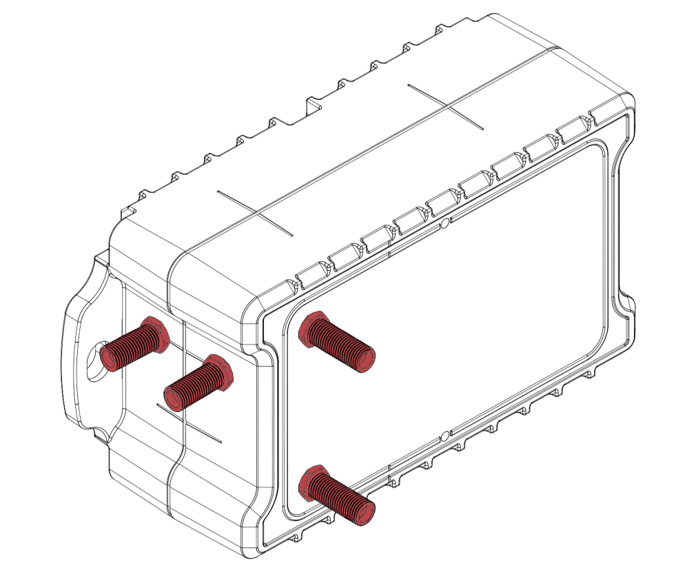
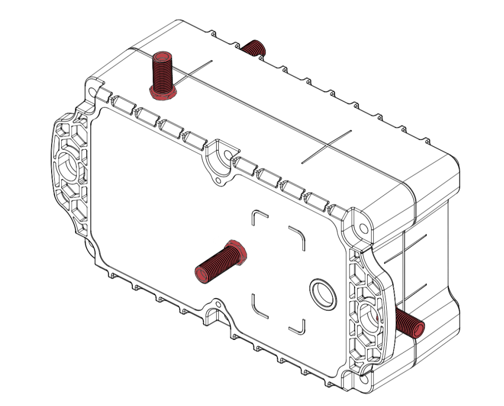
External antenna locations
The IoT Pro caters for seven external antenna locations depending on the orientation of the device after installation
The different external antenna locations are shown below:
Adding an external antenna after delivery
Ensure that no wires are near the drilling location when drilling holes into your device
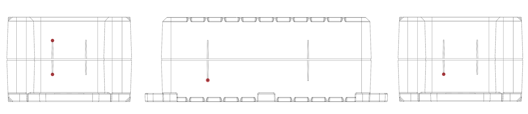
Identify the desired external antenna location.
The different external antenna drilling locations are identified as shown below:
(additional locations are also marked with a groove on the inside of the housing)
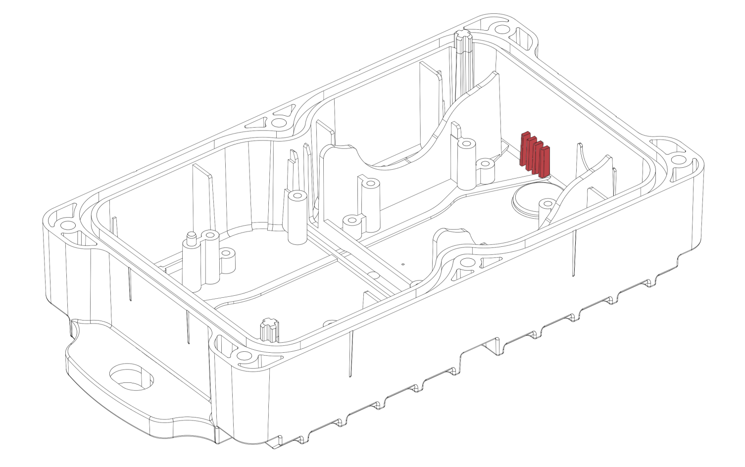
The drilling locations for the external antenna can also be identified by the following features on the inside of the housing:
Open the device as explained in Opening and Closing
Remove all boards inside your device to prevent any damage from occurring during drilling, refer to IoT Pro Assemble and Disassemble Boards
Use a 1 mm drill bit to drill a pilot hole at the end of the feature (as shown by the red marks above)
Use a 7 mm drill bit to widen the pilot hole to the correct size
Remove any plastic burrs from the hole with a deburring tool to ensure that a tight seal is created
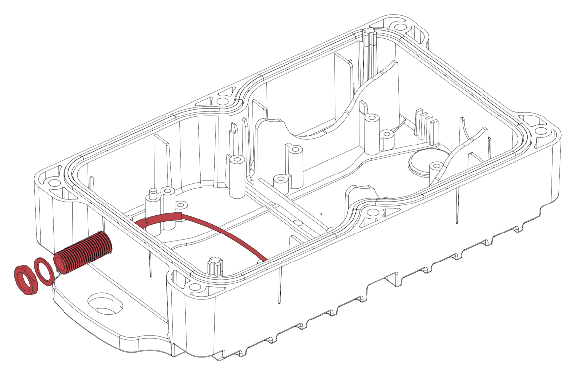
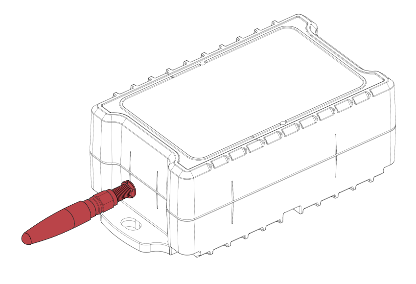
Install the SMA connector as shown, and tighten the lock nut to 1±0.05 Nm with a calibrated torque wrench
You should request IoT to send you the SMA connector, if extras were not already shipped to you and you do not have
The following steps define the process which must be followed to modify the main board to work with the external antenna instead of the internal antenna
The following process must be carried out by a qualified electrician or authorized technician to ensure the external antenna functions as intended
Locate the antenna resistor shown below:
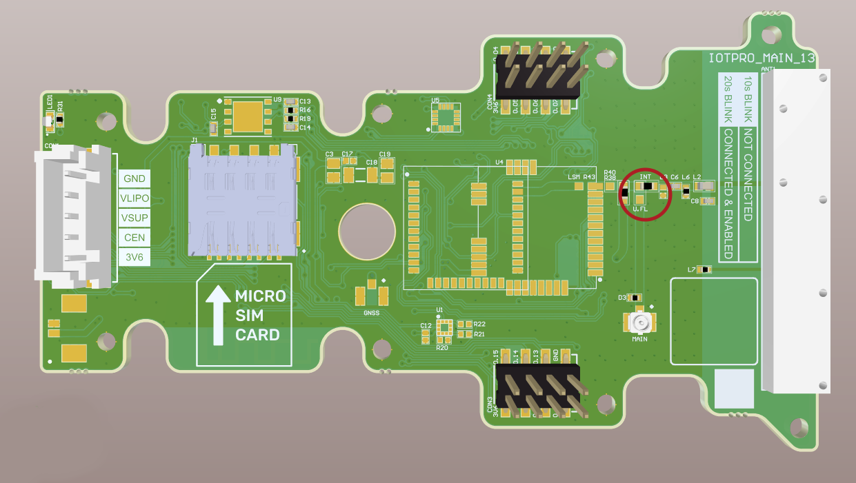
This configuration shows the main board configured to use the Internal Antenna
Apply some solder to the empty pad shown below:
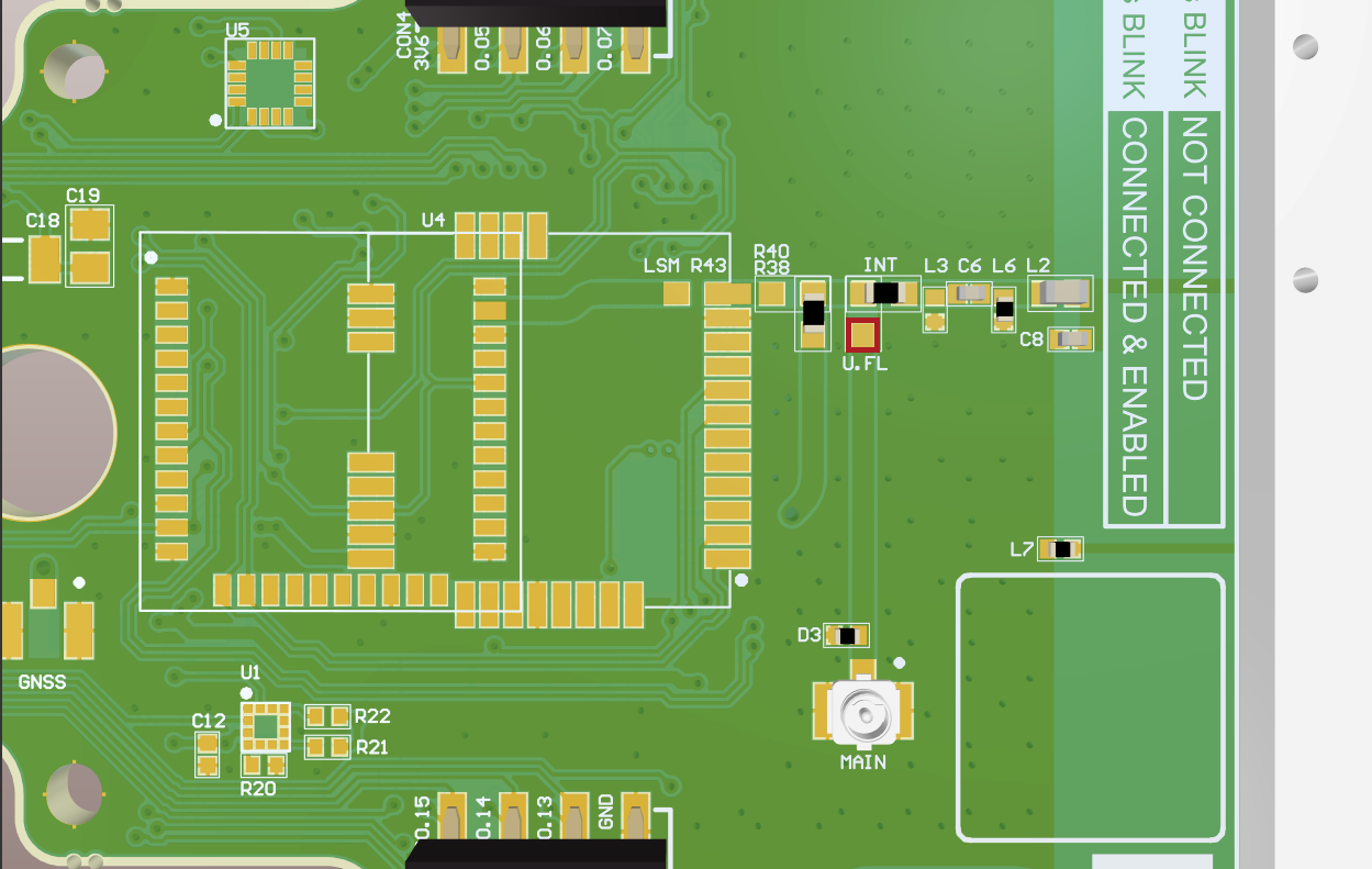
We recommend that soldering tweezers are used in the following steps
Remove the resistor shown in red from its present location
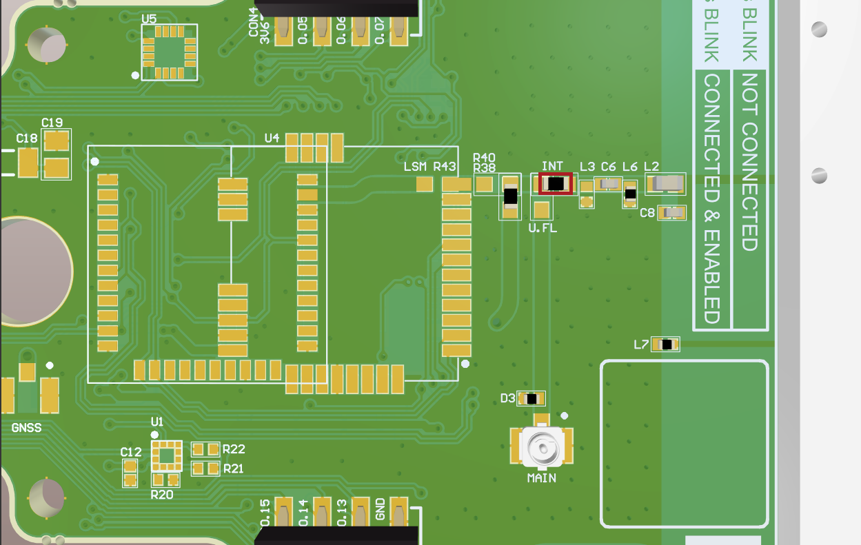
Solder the same resistor in the following orientation:
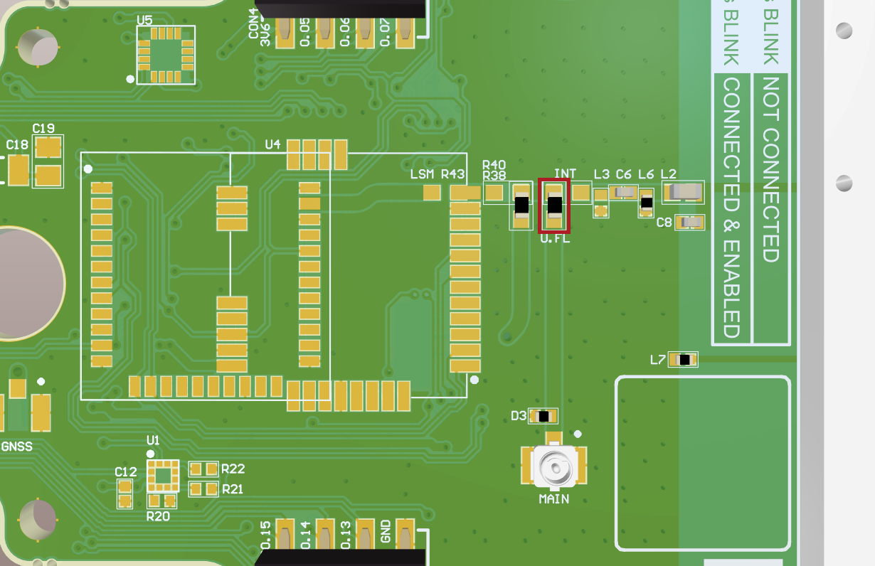
This configuration shows the main board configured to use the External Antenna with the UFL Connector
Check visually that the solder joints are of good quality following IPC-A-610 - Class 2
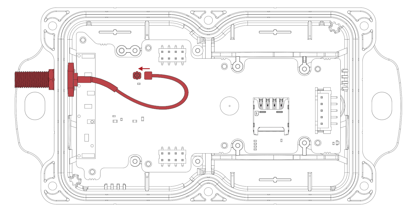
Install the main board (refer to IoT Pro Assemble and Disassemble Boards) and connect the external antenna to the UFL connector shown below:
Re-install the battery or DC Power board (refer to IoT Pro Assemble and Disassemble Boards)
Close the device as explained in Opening and Closing
External antenna options
Four different external antenna types can be provided with your device:
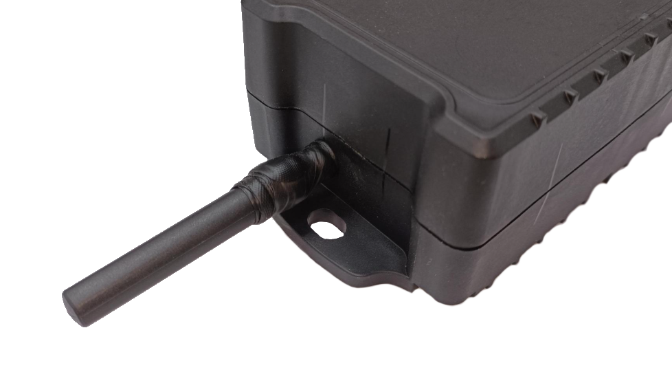
Short-straight antenna
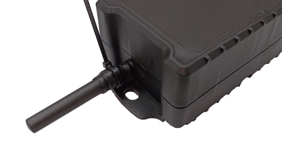
Short-angle antenna
Plastic through-the-lid (TTL) antenna
Through-the-lid (TTL) antenna with acetal protector
Applying amalgamating tape
When external antennas are used outdoors or in a humid environment, amalgamating tape must be applied to the exposed thread portion of the connector to provide additional protection against corrosion
(Unless provided, amalgamating tape must be purchased from the approved supplier: https://eshop.wuerth.com.mt/self-fusing-shrink-tape
Amalgamating tape must be applied to the exposed portion of the thread as follows:
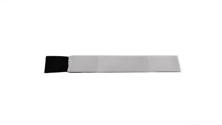
Cut a 15 cm long piece of amalgamating tape (if provided with an entire roll)
Expose a small section of the tape by removing the white plastic sheating
Stretch the tape to apply and start applying from the antenna towards the connector as shown
It is very important to apply the tape in the same direction of rotation as tightening the external antenna, so as not to loosen the antenna by applying the tape in the opposite direction
Continue to stretch the tape whilst applying to ensure that a sufficient seal is created
Once finished, tie a cable tie as shown to secure the loose end of the tape
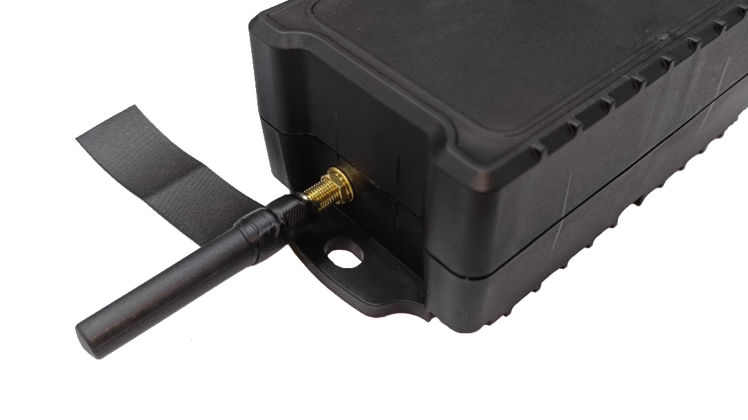
Short-straight antenna
The short-straight antenna is installed as shown
Apply amalgamating tape as explained previously
Short-angle antenna
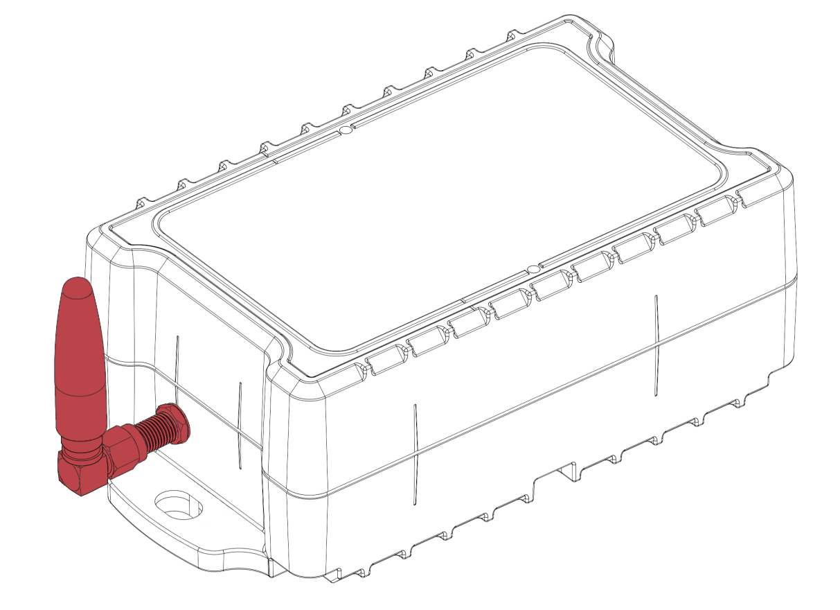
The short-angle antenna is installed as shown
Apply amalgamating tape as explained previously
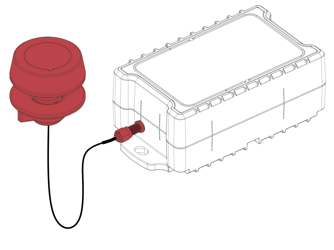
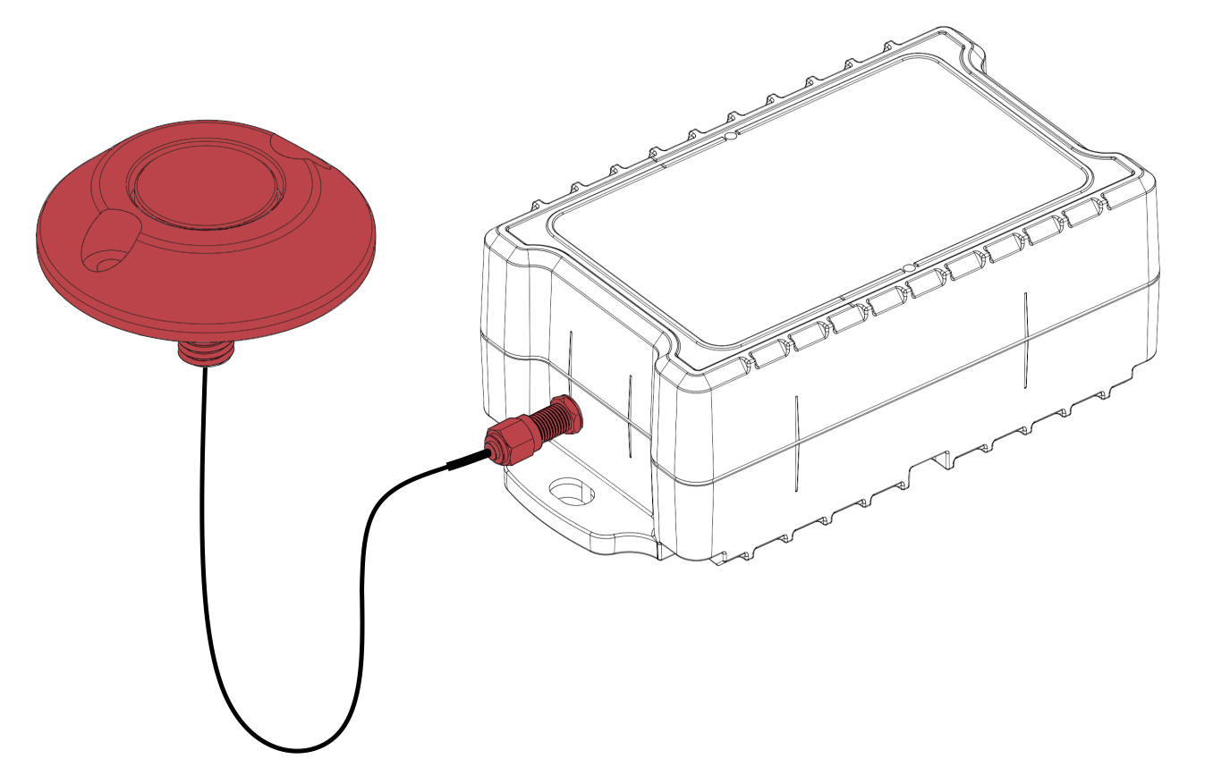
Plastic TTL antenna
The Plastic Antenna should be used when you need a Through the Lid Antenna to achieve better network signal especially if IoT Pro is in a metal box, or under a metal lid and the network is weak, and no major external force like people walking over or cars driving over antenna will be applied to the external antenna.
To install the plastic TTL antenna, first drill a 26 mm diameter hole with a cone drill at the intended location
Remove any burrs with a deburring tool
Remove the nut from the TTL antenna
Ensure that the O-ring remains seated in the designated groove in the antenna body
Pass the antenna cable through the drilled hole
Pass the antenna nut towards the antenna body
Tighten the nut by hand until the base of the TTL body sits flush with the surface
Tighten the antenna connector onto the SMA connector
Apply amalgamating tape to the exposed thread as explained previously
TTL antenna with Protector
The TTL antenna with protector should be used when you need a Through the Lid Antenna to achieve better network signal especially if IoT Pro is in a metal box, or under a metal lid and the network is weak, and a major external force like people walking over or cars driving over antenna will be applied to the external antenna.
To install the TTL antenna with protector, first drill a 13 mm diameter hole at the intended location
Remove any burrs with a deburring tool
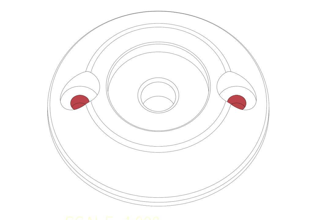
Remove the M12 nut from the TTL antenna and separate the antenna body from the acetal protector
Centre the acetal protector on the 12 mm hole drilled previously and mark the two bolt holes for the protector on the surface of the intended location
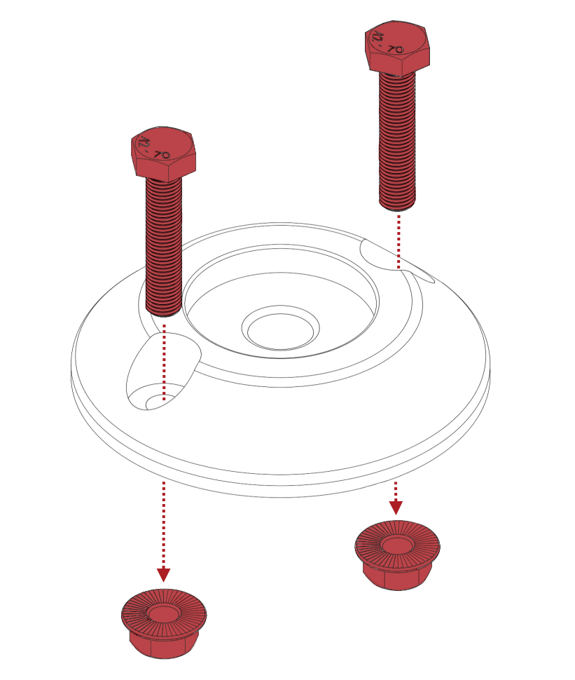
Drill two 7 mm holes at the marked locations
Remove any burrs with a deburring tool
Install the acetal protector with two M6 bolts (length depends on the thickness of the surface) and M6 nuts
Pass the antenna body through the protector
Pass the provided M12 nut towards the antenna body
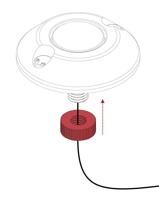
Tighten the M12 nut by hand to secure the antenna body
Make sure that the nut is left slightly loose so force when car drives over is transmitted through the acetal protector and not the antenna neck, which can otherwise break
Tighten the antenna connector onto the SMA connector
Apply amalgamating tape to the exposed thread as explained previously
External coaxial cable extensions
When installing a coaxial cable extension, always apply amalgamating tape to the joints by following the same procedure explained previously
Three different coaxial cable extensions can be provided with your device:
50 cm extension
5 m extension
10 m extension
External antenna bracket
If your device will be installed in a subterranean environment where cell-phone reception is limited, we highly recommend that an external antenna is installed in an opening as close as possible to ground level (such as in a shaft which leads to the ground floor)
In such cases, a bracket can be provided with your device which allows an external antenna to be mounted securely
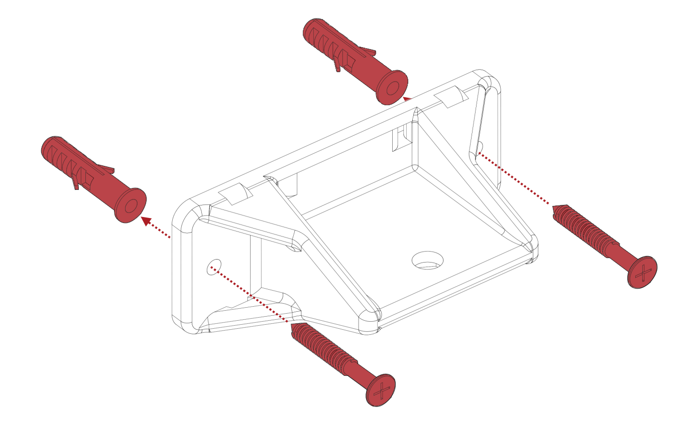
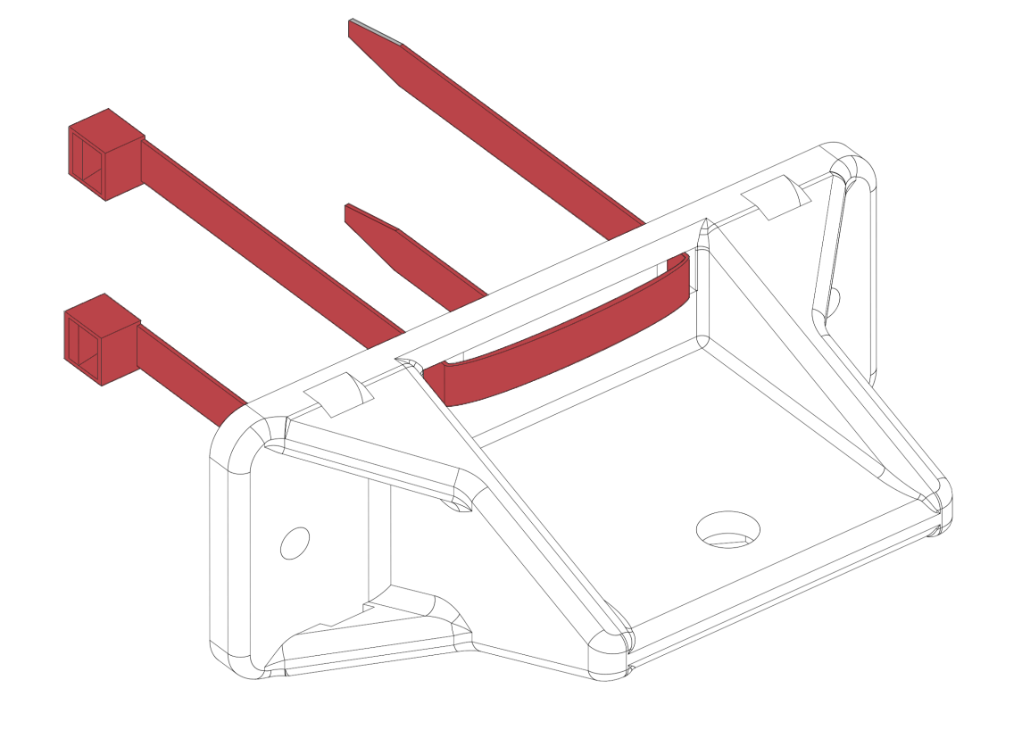
The external antenna bracket can be installed in three different ways:
Using 2x plastic anchors/ M4 self-drill screws/ M4 bolts and nuts (kindly specify the surface to which the bracket will be installed so that the appropriate fasteners are provided)
Using 2x cable ties (length depends on the installation requirements) to install the bracket to a horizontal fixture
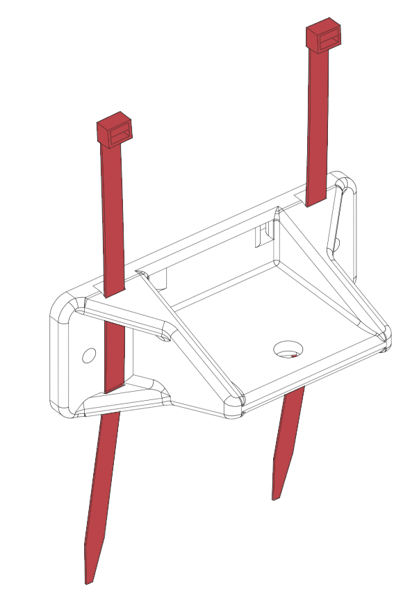
Using 2x cable ties (length depends on the installation requirements) to install the bracket to a vertical fixture
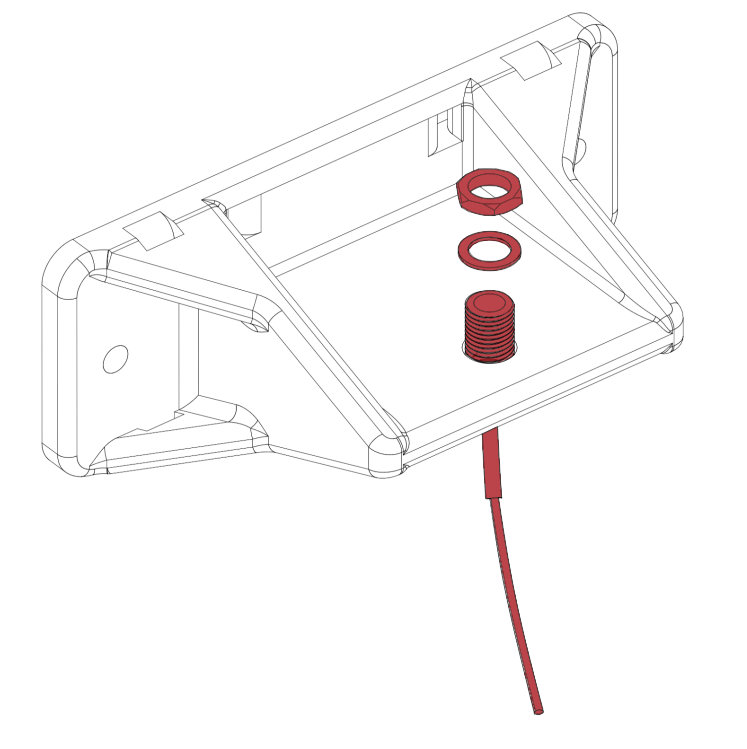
To install an external antenna onto the bracket, first apply amalgamating tape to the male end of the coaxial cable extension as shown:
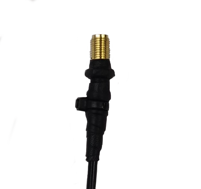
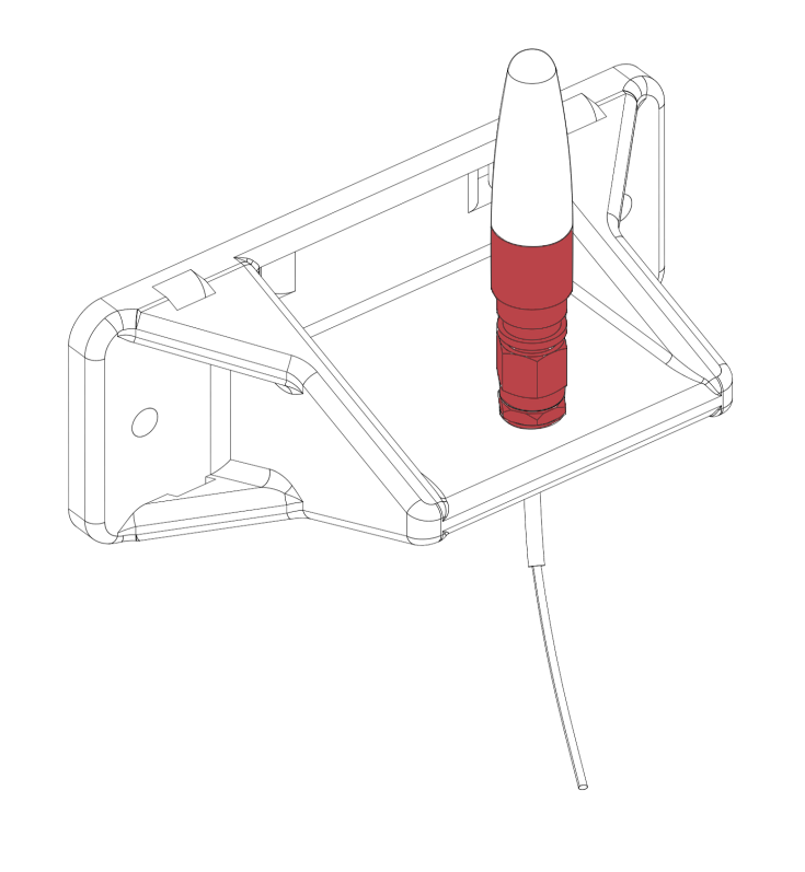
Install the male end of the coaxial cable extension onto the bracket as shown:
Install a short-straight antenna and tighten by hand
Apply amalgamating tape as explained previously, from the antenna down to the coaxial cable connector (shown in red)
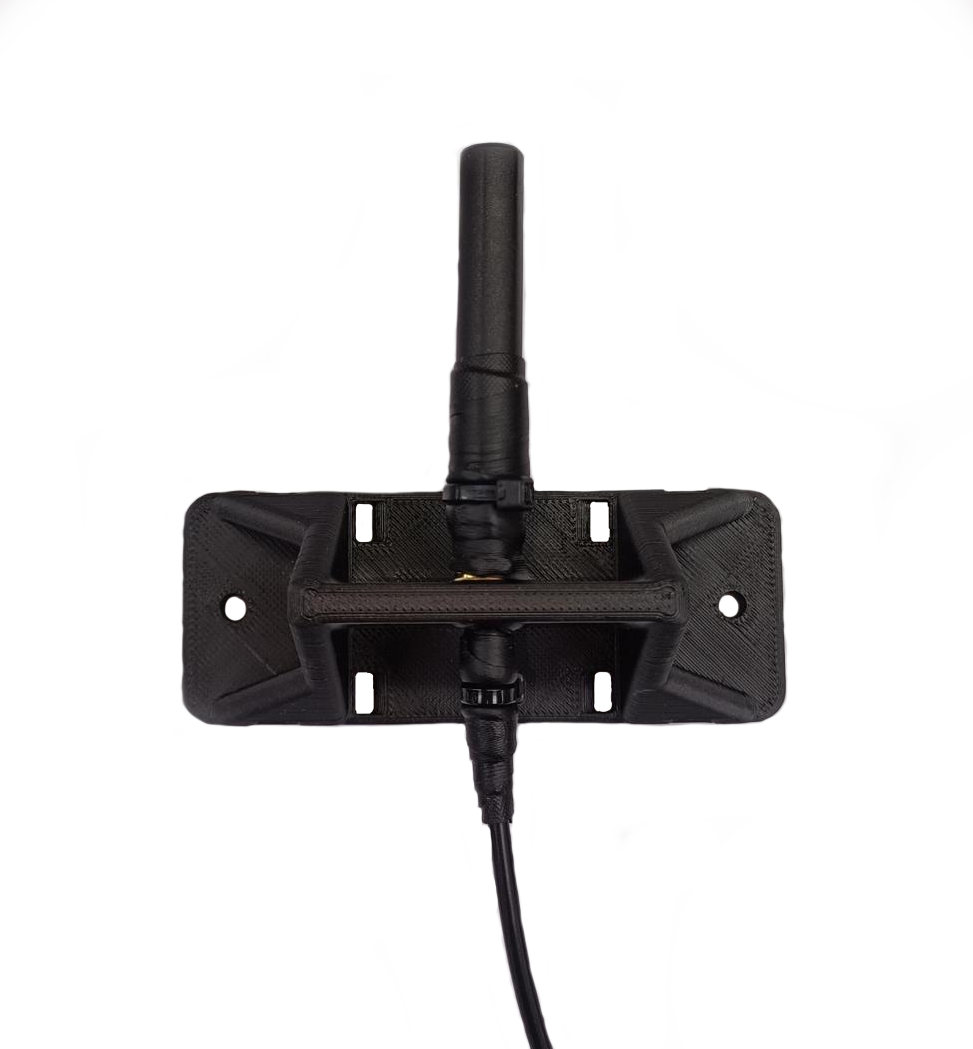
Connect the female end of the coaxial cable to the SMA connector on your device
Apply amalgamating tape to the exposed thread as explained previously